Project BOTomazov ( self-portrait drawing robot )
Named after Alexander Bogomazov (1880 – 1930), a Ukrainian painter and artist known for Cubo – Futurism and Spectralism artistic styles, and also for setting theoretical foundation of modern art.
DEMO:
Project Advisors: Gregg Wygonik (Microsoft)- @gwygonik, Andrei Kashcha (Amazon)- @anvaka
Project Motivation:
Abundance of CNC machines is on the rise due to lower cost of components that make up these CNC machines. Even though there is a variety of open source software packages available to control these machines, most of them depend on a human to create the design before it could be sent to the machine for further operations like milling, cutting or 3D printing.
The vast majority of consumer grade CNC machines like laser cutters or 3D printers operate by reading a set of instructions from a specially formatted text file and executing those instructions. Because machines simply execute instructions line-by-line, they are not burdened by the complexity of the underlying design.
In this project I wanted to explore interactive ways to create very complex designs by using data sources such as image sensor data (camera). I set out to build hardware and software that a person can interact with to create drawings of “selfies”, for the following reasons :
- There is a wide range of CNC machines that can work with drawings generated by my software
- This project sparks my interests within robotics and within user interface design
- The resulting technology combination has many potential uses that could be explored in the next phases of my education at MSTI
Technical Implementation:
In short, BOTomazov is a combination of a CNC Machine (drawing robot) and software driving the robot. The software is designed to capture a photo from a web camera and turn that photo into a drawing that is performed by the drawing robot. Because robots are just executing a set of instructions, the drawing is made to be complex, almost impossible for a human to draw by hand.
For the particular style of drawing, I chose to turn a photo into a set of horizontal lines with the following algorithm, inspired by Gregg Wygonik’s SquiggleDraw:
Retrieve photo as an array of pixels IMAGE
Set desired number of horizontal lines as LINE_COUNT
Set desired number of vertical spacing as SPACING
Set desired line amplitude as AMPLITUDE
Set desired line rotation frequency as FREQUENCY
For y :=0 to image height step image height / LINE_COUNT do
	Set startx := 0
	Set starty := y
	Create a set of coordinates as [startx, starty]
	For x := 1 to image width step SPACING do
		Get brightness br of the current pixel as average of r,g,b values
		Set r := (255 - br) / LINE_COUNT * AMPLITUDE
		Set a := (255 - br) / FREQUENCY
		Create a set of coordinates as [x, y + Math.sin(a) * r]
Pass the resulting array of coordinates to rendering application
Below you can see an input image and a drawing that’s generated using this algorithm:
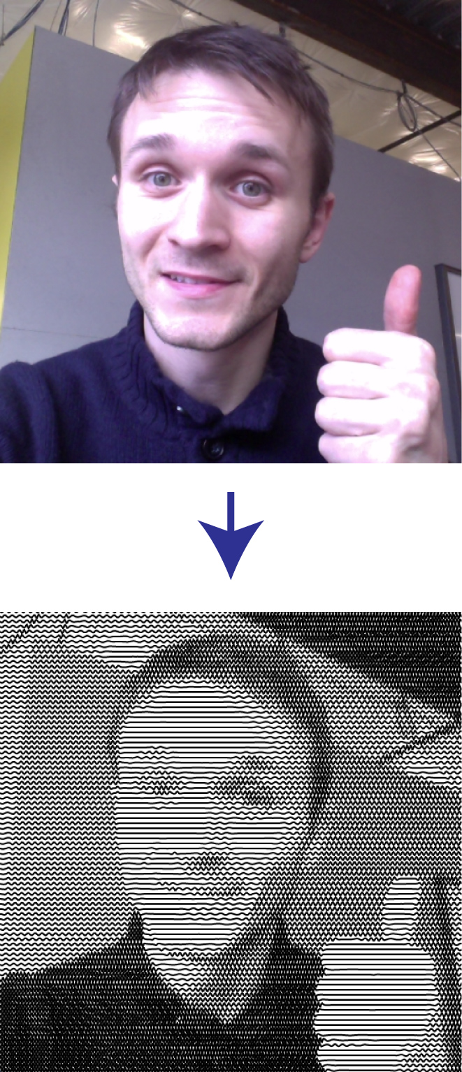
SquiggleCam processing example
BOTomazov consists of the following components:
- Camera (WebCam)
- Client UI that captures user input (desired drawing settings) and translates captured photo into SVG (scalable vector graphics) files using modified and optimized SquiggleDraw algorithm
- Server component that accepts vector files from the client UI and processes those files into set of instructions for the CNC machine (GCODE)
- Server component that connects to the CNC controller via serial interface and feeds generated GCODE into the controller
- CNC controller that accepts GCODE from serial interface and translate the GCODE into motor movements
- 2 Stepper motors for X, Y dimensions
- 1 Servo motor for raising and lowering the pen
- CoreXY topology, belt-driven mechanism to position the pen in X and Y dimensions
Functional Diagram of the whole system is presented below:
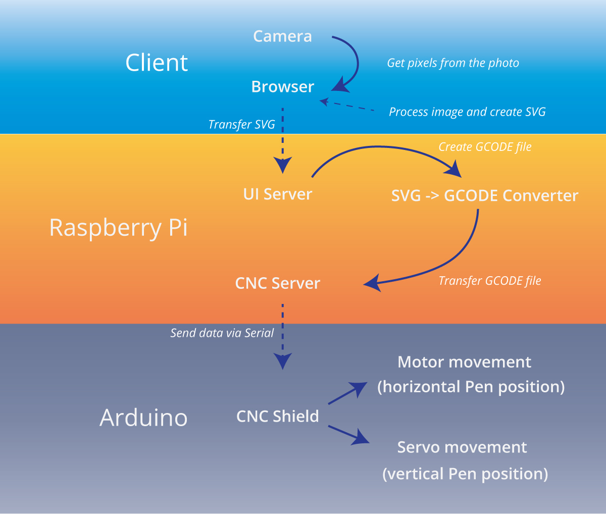
Arduino RaspberryPi Plotter diagram
The following technologies were used to creating BOTomazov hardware and software:
- SVG was used as the file format for resulting drawings
- D3 was used as a render engine for the intermediate SVG representation
- SquiggleDraw algorithm was used as a basis of my image processing algorithm
- Node.js was used to run a server that stores SVGs generated from the UI
- CNC.js was used to connect to the CNC machine via serial interface
- WebWorkers were used to parallelize image processing in the browser (execute JS on a separate CPU thread, freeing up CPU cycles for user interactions)
- Arduino + GRBL were used as CNC controller
User Interface:
BOTomazov’s user interface consists of the following components (that could be seen in action here: https://youtu.be/TN1vsZTuDFk ):
- Sliders to change various line drawing settings
- Camera preview
- Drawing preview
- Action buttons (Capture, Draw, etc)
- Notifications
Below is a screenshot of the user interface, as it appears on a tablet that also acts as a camera for “selfies”:
Changing the values of the sliders affects the resulting drawing in the following way:
- Line count controls how many horizontal lines there are
- Pixel Spacing controls how many pixels to analyze horizontally on each line (spacing of 2 pixels would iterate over every other pixel in the horizontal line)
- Amplitude controls the height of each line at its maximum and minimum
- Frequency controls the angle of the curves (how frequently the curves appear on the line)
- Brightness controls the camera image brightness, affecting the straightness of the lines
- Contrast controls how evenly distributed curves and lines are
For example, here’s the rendering of the same image with a high number of horizontal lines on the left (90 lines) and low number of the lines on the right (45 lines):
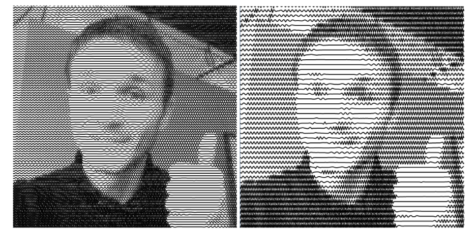
SquiggleCam parameters
Please see this video below for a quick overview of all sliders:
Evaluation:
For the evaluation of the product I chose two users to try to interact with the user interface and set up the following tasks that help me understand whether the product is useful and which pain points it currently has:
- The user should be able to open the web application with minimal instructions
- The user should be able to take a picture with the tablet
- The user should be able to explore the various settings without any instructions
- The user should be able to send the picture to the robot without any instructions
For each of these tasks I set up the following criteria of evaluation:
- How fast the user was able to execute the task
- What the user said during execution of the task
- What improvements the user suggested for each task
- General feedback about the product
Evaluation Results:
I performed an evaluation with three users and consolidated their feedback as follows:
- The user interface does not need so many options.
- Instead of complicated language, the sliders should have simple text like “Less squiggles”, “More squiggles”, “Less Lines”, “More Lines”.
- The user interface was easy to use after initial confusion about the language presented
- The users wanted to tinker will all options and to see what the effects of their interactions are
- All three users were excited to get their portrait and wish the process of drawing was faster.
Potential Improvements to this product:
- Change the language and reduce the quantity of options in the UI
- Replace pen with a laser and enclose everything in a small portable box
- Create faster application to preview the images
- Create a variety of styles of drawings
Reflection:
Choice of the problem:
I chose this problem because I noticed a lack of tools for making complex designs for CNC machines and saw potential in using web technologies for creation and testing of complex drawings. I wanted to study creation of the whole pipeline for a CNC machine that could be later developed into a complete product:
UI (Browser) -> Micro computer -> CNC Controller -> Motors
During this process I have achieved the goal of creating hardware and software from scratch and developing a functional platform that can be extended and transformed into more practical CNC applications.
Choice of hardware and software tools for implementation:
I chose Javascript and Python as main languages for the whole project for a few reasons:
- I can easily navigate the existing code repositories and leverage libraries that are already created for the functionality I needed
- Javascript can run in a browser on a tablet that acts as a selfie camera, reducing the time to create the application in a short timeframe
- SVG, scalable vector graphics standard is a well-developed standard that works in almost any web browser and also translates well to GCODE
- Arduino and GRBL were chosen because GRBL is a solid library with hundreds of thousands users
- CNC.js was chosen because it can drive an Arduino via Serial interface and has easy to use API that I could connect to
- CoreXY mechanical platform was chosen because most parts for it can be 3D printed and the rest can be purchased on a low budget
Choice of evaluation metrics:
I chose to give the users a minimal set of instructions and listen for their voice-over on every step of the way during the evaluation so that I could consolidate that feedback and improve the application.
The user-facing application had only one screen but even then, during the evaluation I discovered that there could be some confusion over certain UI elements. In the future I’d start designing and testing in more iterative way.
Time management:
I spent many weeks working on this project, sometimes getting carried away by optimizing the software for greater speed. I also made sure to meet in person with some experts behind the algorithms that I was using and get their permission for use in my project. That was one of the most beneficial things for me personally because I got to talk to people that inspire me.
This was a heavy project for one person because it contains a lot of moving parts (no pun intended). Because of complexity, each week I created a todo list of tasks that would bring me closer to completion of the whole system. I had to stay up very late a few nights to manage the bugs and to implement improvements that were on my list.
UPDATE:
Published source code for the SquiggleCam, a browser based software that takes image as an input and generates line drawing to approximate the image. The resulting SVG file can be used on a pen plotter, laser cutter or other CNC machine!