Single phase Micro Brushless Motor
Original idea started here: http://www.rcgroups.com/forums/showthread.php?t=596219
Concept
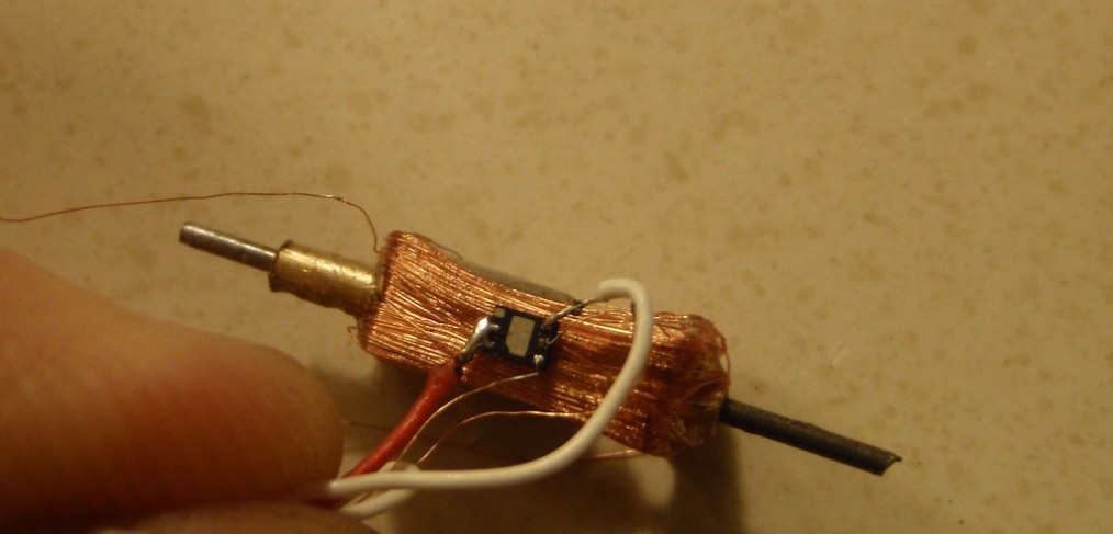
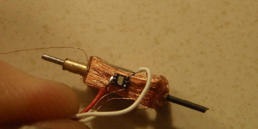
A single phase brushless motor consists of a magnet and a coil, bushings (serve as bearings) and A1442 part from Allegro. If a current is applied a torque is generated having a sinusoidal form as function of the angle. At the points where the torque becomes zero the direction of the current has to be reversed. The inertia of the rotating part is large enough to overcome the zero torque section. The motor is running if the switching is done at the right moment. It does not matter, if the magnet or the coil is rotating. Here only rotating magnets are considered.
How can we detect the switching points? The easiest way is a sensor which senses the strength of the magnetic field: a Hall-Effect sensor that is inside A1442 part.
Here is connection diagram for the A1442:

he present design will rely on a Hall-Effect sensor. Switching is achieved by a transistor bridge. Fortunately a chip is available now combining the Hall-Effect sensor and the bridge in a 2x2x0.5mm housing, weighing just 6mg A1442 and A1441 from Allegro. This small unit has an internal resistance of 6Ohm which has to be taken into account when designing a motor.
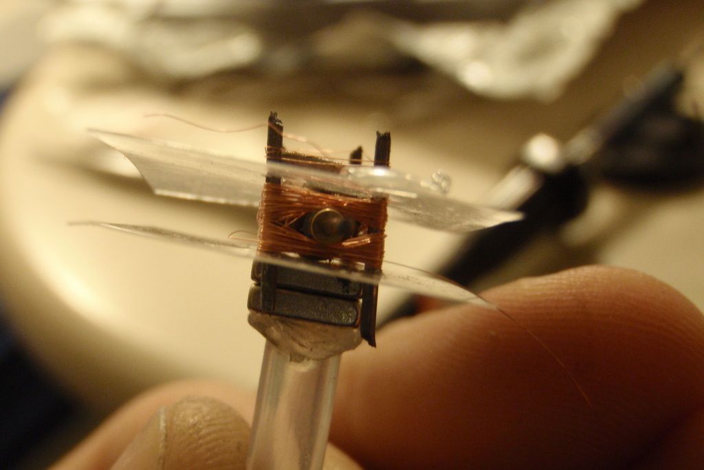
The smaller the air gap the better. You can make also 2 coils placed diametrically next to the magnet.
Generally, torque is proportional to current, turns and area of a coil in the magnetic field. The magnetic field is strongest at the cylindrical surface.
T = m X B (vector product of magnetic diople moment m and magnetic field B)
where B is the field of the coil. B again is proportional to N * I / L where N is number of turns and L is the length of the coil. So B does not depend on the diameter of the coil. Thus, a larger air gap due to larger diameter does not decrease the torque, as long as the current I is equal, but a larger diameter causes a higher resistance and so lower current for equal driving voltage and more weight.
The torque generated by a winding in a magnetic field is T = B*A*I with B = average magnetic induction (Tesla), A = area of winding and i = current flowing through the turn.
The control of the complete motor is achieved by limiting the on time per 180 degrees, i.e. the duty cycle is according to the signal of the receiver.
Build Process:
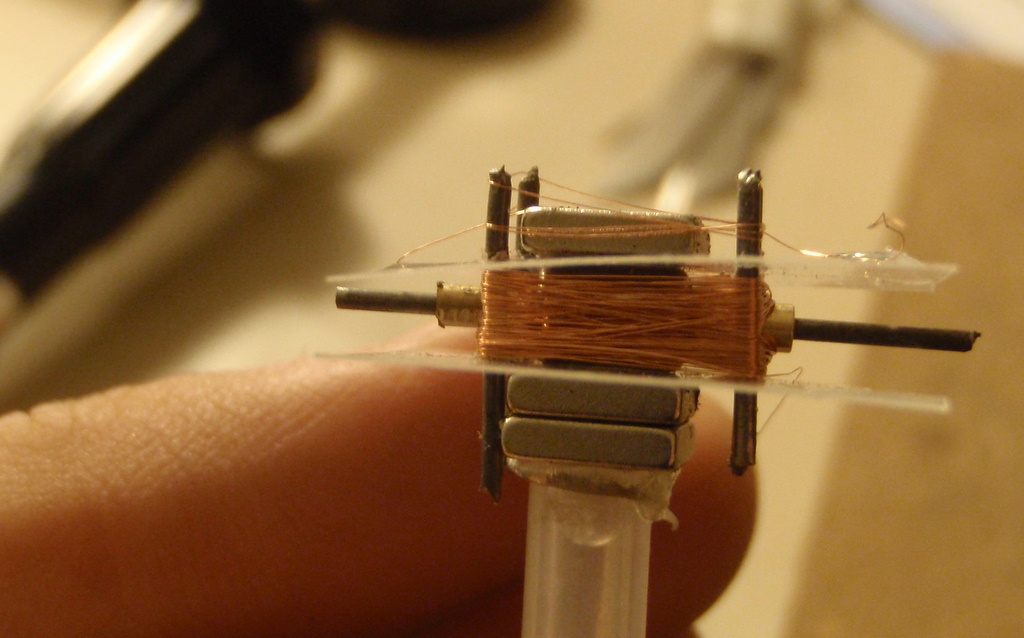
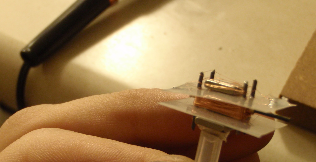
Video

where to find such a chip
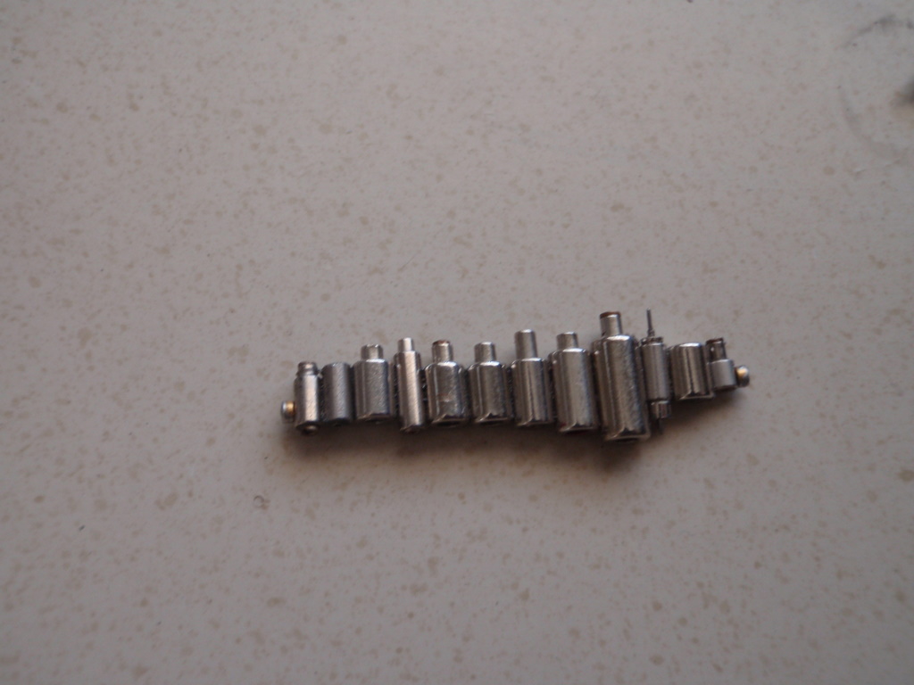
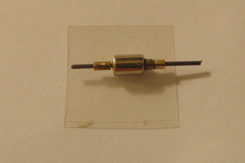
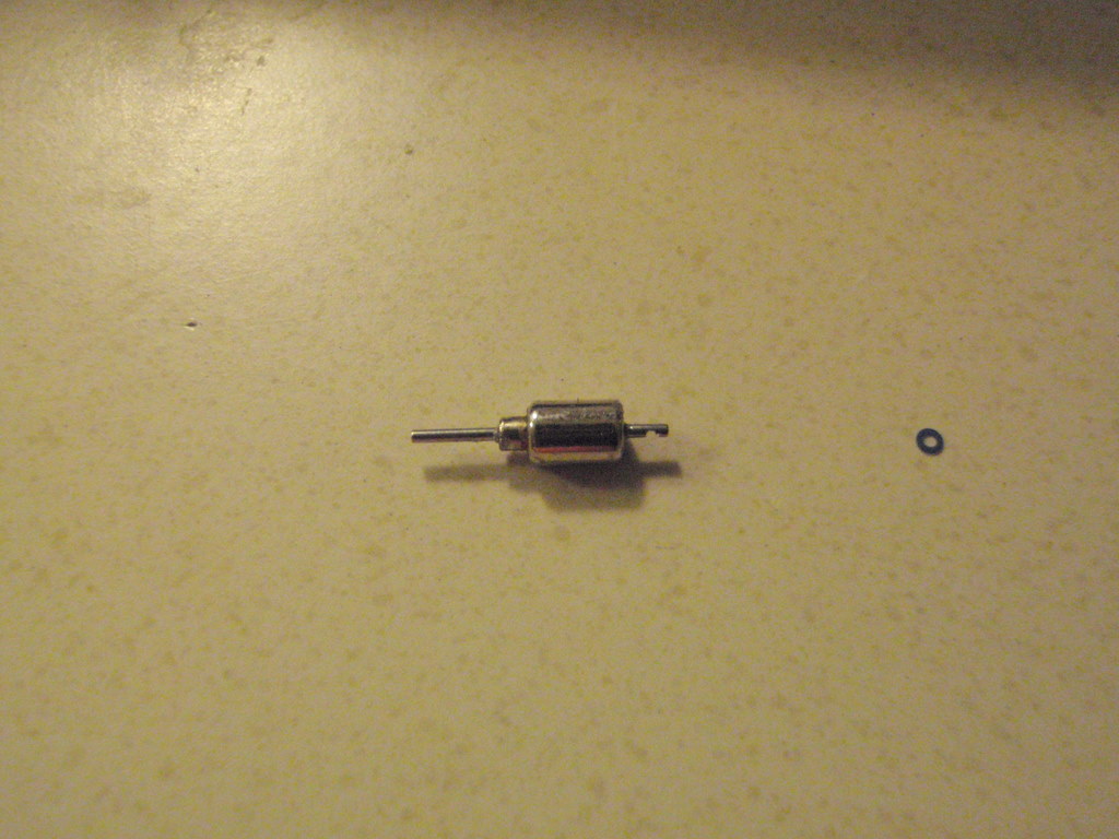
what type of magnet is used
Just a small neodymium magnet from another micro motor (for example from a tail motor from a mini rc helicopter)
Hey.. The chip A1442…is there a substitute? I couldn’t find a substitute and don’t want to buy from Digikey as the shipping is too expensive.
Unfortunately I haven’t found a substitute to that chip… Sorry!